Guide to Installing IDE/ATA devices
The vast majority of hard drives
sold today for PC computers are IDE or sometimes referred to as
ATA drives. That is why we are going to discuss IDE drives.
IDE CHANNELS
Motherboard chipsets on today's motherboards support two channels
or two connectors. Yes, there is new technology arriving
on the scene that provides for four channels, but that is outside
the scope of this discussion. So, the normal motherboard has
two connectors, one for each channel that data moves through to
the motherboard. Each of these channels supports two IDE hard
drives, set one as Master and the other as Slave. I
need to mention at this point that there exists other devices that
will connect as IDE devices, such as Internal Zip drives and Internal
CD Rom drives. These IDE devices are all configured the same
as a hard drive. So for now we will concentrate on IDE hard
drives. This is a diagram of a Master and Slave configuration
on an IDE channel:
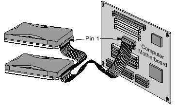
Master and
Slave drives
Both drives share one ribbon data cable back to the controller,
in this case the controller is part of the motherboard. In
order for the drives to reside together on a single ribbon cable
using one channel, either the Primary channel or Secondary Channel,
the drives must be configured, one as Master and the other as Slave.
This effects how they will be displayed and used by the computer.
The Primary Master drive is always "C", except possibly if a SCSI
controller is involved, but that is outside of this discussion.
Then the Primary Slave drive is the "D" drive, as the Secondary
Master is the "E" drive and the Secondary Slave is the "F" drive...
or like this:
- C drive = Primary
Master
- D drive = Primary
Slave
- E drive = Secondary
Master
- F drive = Secondary
Slave
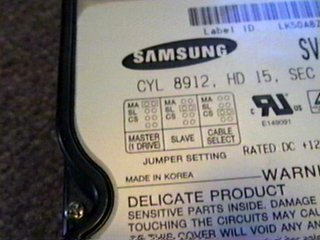
Configuring an IDE drive to be either Master
or Slave is done with the jumper pins on the drive, these pins are
nearly always between the Power connector and the IDE ribbon cable
connector. Each manufacturer has different pin configurations
for either Single drive in a computer, Master or Slave. Most
often Single drive and Master are the same setting. You simply
determine the jumper settings from
the hard drive manufacturer's
web site, from the installation manual or right on the drive
label, such as this:
Then, using a pair of needle nose
pliers, you can move the jumper to the proper location, remembering
that nearly always the drive comes from the factory set as a Master
drive:
Mounting
the Drive
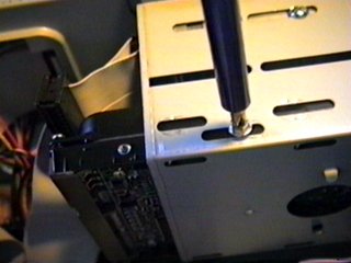
The drive is now ready to be installed into the computer case.
The drives are either 3.5" wide or 5.25" wide. Inside the
case are bays to hold both sizes of drives. Simply slide the
drive into the appropriate slot, then using the screws accompanying
the drive, fasten the drive into place. Be careful not to
over tighten these screws, as they will easily strip out the threads
in the drive and always use the appropriate screws to mount the
drive.
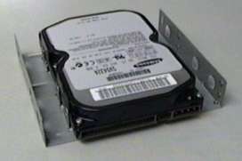
If you do not have any available
3.5" bays available to mount the drive, there are kits available
to hold the drive in the 5.25" bays. This is a picture of
just one type available.
I should also mention some computer
cases, such as Enlight, have special hard drive brackets inside
the case that are not usable for floppy or zip drives due to their
location. I particularly like this arrangement, as the drives
are totally separate and allows for better air movement around the
drives.
Ribbon Data
Cable
Now that the drive is seated in the case and fastened, it is time
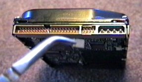
to attach the Ribbon Data cable. The ribbon cable normally
has three 40pin connectors, one for the controller and two for hard
drives, master and slave. Since all motherboards since the
advent of PCI 486 motherboards have included onboard IDE controllers,
we will consider that the controller is on the motherboard.
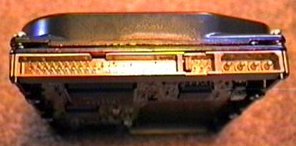
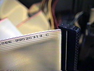
The controller connectors on the
motherboard should be labeled as to the location of Pin#1.
If you cannot find the marking on the motherboard, refer to the
motherboard manual or visit the
motherboard manufacturer's
web site for these locations. Once you have determined
pin#1 on the motherboard, attach the ribbon cable with the stripe
side adjacent to pin#1 on the controller connector. The strip
is usually red, but can also have writing along the edge:
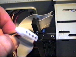
Now, we connect one of the other
connectors on the ribbon cable to the hard drive into the 40pin
slot. We also need to be sure that the stripe side of the
cable is adjacent to pin#1 on the drive. If you are unsure,
refer to your hard drive manual again. Usually, pin#1 is the
side toward the power connector.
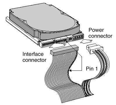
Power Cable
The only remaining cable to connect is the power cable inside the
case. Find a power connector that matches the drive's connector
and press it into place. It will only go into the connector
one direction, based on the design of the plug and connector.
CMOS Identifying
the Drive
We have the hard drive installed and it is time to determine if
we have done it right. Making sure we have at
least the monitor and keyboard connected to the computer, turn it
on. At the appropriate time, usually during the POST phase,
(this is the first phase of starting the computer and usually when
the memory test is displayed on the screen). Press the appropriate
key combination to open the CMOS settings in the BIOS. Nearly
all motherboards made in the last few years now use [DELETE] key
to open the CMOS.
In the CMOS, you will find a setting
to AUTO Detect IDE hard drives. Using this utility,
the BIOS should detect the hard drive. Now, all is left is
to exit the CMOS, saving the new settings and your installation
is complete.
If the CMOS does not detect the
new drive, you will need to turn off the computer, (this is alright
even if you are in the CMOS, as it will not save any changes).
You need to check that the ribbon cable is properly installed, with
Pin#1 connected to the stripe side of the cable, you need to be
sure the power connector is tightly in place and you need to verify
you have set the jumpers on the drive for the appropriate Master/Slave
configuration. All of these issues must be addressed and verified.
One more thing you may try, if these all seem correct is to turn
the IDE Ribbon Data cable connector around on the drive.
Okay, the CMOS still does not
find the drive? When you turn on the computer, does
the hard drive spin up... do you hear it spinning? If
so, power is not an issue. Try replacing the IDE Ribbon Data
cable. Still no success? Then the final though is you
have a bad hard drive. This is extremely rare, though I have
seen it on a few occasions. Time to return the drive for replacement.
But, for our discussion...
if you have done every step as listed, your system should now have
the hard drive installed. The next phase is to Boot the computer
with a boot disk and partition, then format the drive.